The History of LUNA
Note: This is a crosspost of a Cynthion update on Crowd Supply: https://www.crowdsupply.com/great-scott-gadgets/luna/updates/the-history-of-luna
Starting Great Scott Gadgets
Ten years ago this summer I quit my day job at a radio research lab and made Great Scott Gadgets (GSG) my full-time job. I dedicated myself and the company to our mission: to put open source tools into the hands of innovative people. One of the first things I did at that time was to make a list of products I was interested in making. That list included “USB swiss army knife”. I didn’t know how to make such a thing at the time, but it was something I had in mind from the start. I soon started referring to the concept as “usbstar” in my private notes and envisioned that it would be shaped something like a three-pointed version of the Throwing Star LAN Tap. I wanted it to have three points with one USB port each for implementing Meddler-in-the-Middle (MitM) or active monitoring. One port would be connected to a target host, another to a target device, and the last to the monitor/control host.

A year later I hired Dominic Spill. Around that time Travis Goodspeed released his Facedancer software along with hardware based on his GoodFET project. Facedancer was exciting because it allowed rapid development of USB devices in Python, making it highly useful for security testing of USB hosts.
In 2013, Travis, Dominic, and I had a chat in a pub where we discussed ideas for next-generation Facedancer hardware similar to the usbstar concept. We thought that we could make a microcontroller-based platform similar to GoodFET with two or three USB 2.0 ports that would be faster and more capable than the target USB port on Facedancer. In that conversation, one of us (Dominic, I think) first proposed the name “GreatFET” for a Great Scott Gadgets variant of GoodFET, although we imagined at that time that GreatFET and Facedancer would be two different hardware platforms.
Daisho
After releasing HackRF One, we had expanded the usbstar idea into a greater vision that became Daisho. This project had an FPGA-based mainboard with pluggable modules, each for a different high speed communication technology: one for SuperSpeed USB 3.0, one for Gigabit Ethernet, and one for HDMI. It was a big project, but, thanks to some outside funding, we were able to hire help.
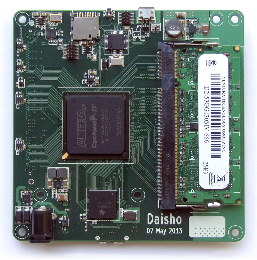
With Daisho we implemented SuperSpeed USB MitM capability, demonstrated by Jared Boone who designed both the mainboard and the USB module. It was only just working in time for the demonstration, but it was an effective proof-of-concept of FPGA-based USB MitM.
When our funding for Daisho ran out, however, we realized that we had created a good tool for our research but hadn’t created a viable product. We felt that Daisho was too big and expensive to have much hope of commercial success in our community. It was an overly ambitious project, but we learned a lot in the process.
One nice thing that came out of the project was the Daisho USB 3.0 device core developed by Marshall Hecht. This was the world’s first open source USB device core for FPGAs, and it has since been ported to other platforms and used in actual products.
Around the end of the Daisho project, Dominic visited the GSG lab in Colorado for some project planning. In a brainstorming session, he, Taylor Streetman, and I sketched out a usbstar design together: It had an FPGA in the middle, surrounded by three USB 2.0 PHY chips. The idea was to take what we had learned from Daisho but to scale its USB capabilities down to a single board that was simpler and more affordable.
We wanted to start working on it immediately, so I ordered an FPGA development kit to arrive during Dominic’s visit. By the time the kit arrived, however, we had talked ourselves out of the project!
One reason we didn’t pursue the usbstar concept at that time was that neither of us had very much FPGA experience. Without external funding to hire folks like those who had helped us with Daisho, we felt our progress would be slow. We also weren’t excited about building an open source product that relied on proprietary (and in some cases expensive) FPGA development tools. We liked the idea, but we prioritized GreatFET instead.
GreatFET
Another reason we abandoned usbstar was that we had expanded our vision for GreatFET. Instead of the minimal microcontroller I had used in my initial prototype, we chose the LPC43xx series that we had used in HackRF One. With this part we were able to place two USB interfaces on GreatFET One with potential for a third USB port on an add-on board (called “neighbors” in honor of Travis). By making GreatFET “greater” in this way, we tried to enable the most important capabilities of the usbstar concept without having to additionally pursue the FPGA-based project. While GoodFET and the original Facedancer hardware were two different platforms, GreatFET combined those functions into a single board.
While we were developing GreatFET, Dominic started collaborating with Kate Temkin on some USB projects. Kate single-handedly ported/rewrote Travis’s Facedancer software for GreatFET One and other platforms, and the two of them worked on GlitchKit and USBProxy. We hired her as a contractor to develop USB training courseware and GreatFET software, and she eventually joined us as a GSG employee.
Not long after joining the GSG team, Kate started developing Rhododendron, a GreatFET neighbor for High-speed USB analysis. Rhododendron was designed to be the simplest, lowest cost circuit for passive monitoring of High-speed USB. Kate and Mikaela Szekely demonstrated Rhododendron at Teardown 2019 along with ViewSB, their new USB analysis software.
LUNA Hardware
In the months following that demonstration, we worked toward manufacturing Rhododendron, but Kate started questioning whether or not it was really the best approach. Rhododendron was designed to be ultra-low-cost, but it additionally required purchase of a GreatFET One. She began thinking about making a much more sophisticated and capable tool in the same price range as the combined cost of GreatFET One and Rhododendron.
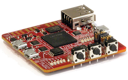
We didn’t see Kate at the lab for a couple weeks late in 2019, and then one day she appeared and announced that she had designed a new USB multitool. LUNA was born! She showed us the design, and I immediately recognized the FPGA-based usbstar concept that Dominic and I had sketched several years prior. Design work we thought would have taken us months Kate had accomplished in two weeks! Additionally she had included a fourth pass-through port for passive monitoring, making LUNA a hybrid of usbstar and Rhododendron.
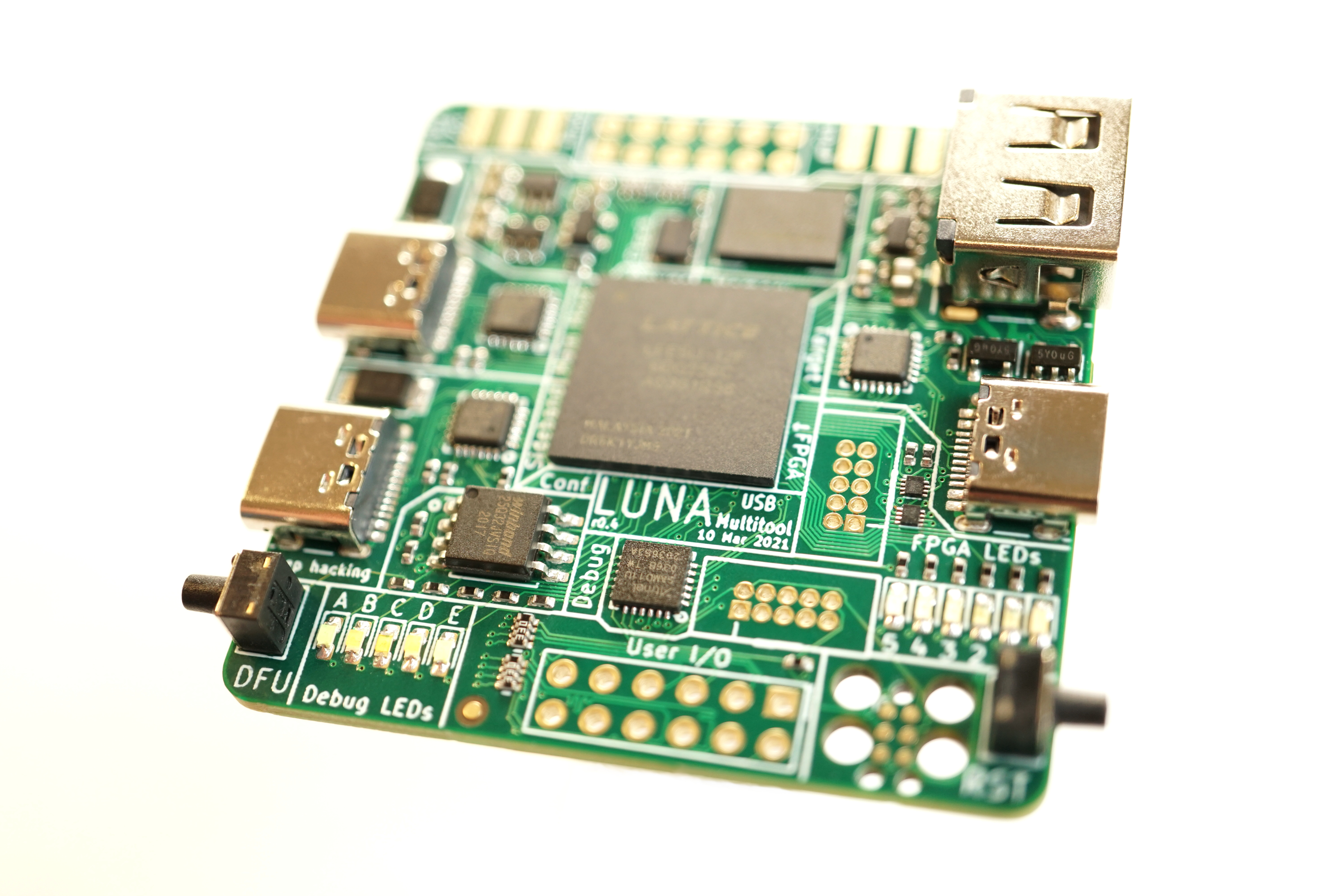
One of the exciting aspects of Kate’s initial design was that LUNA was based on the ECP5 FPGA which had only recently become supported by an open source toolchain thanks to gatecat and other members of the open source FPGA community. We felt that, with the availability of open source tools, the time was finally right for GSG to make an FPGA-based design. The ECP5 was a perfect choice for LUNA as it has the performance necessary for multiple High-speed USB interfaces at a low cost.
Another thing that excited us about LUNA was Kate’s vision for gateware based on whitequark‘s nMigen, combining the flexibility and power of FPGAs with the rapid development of Python.
The Impact of COVID-19
Sadly, at about this same time the SARS-CoV-2 virus that causes COVID-19 first infected humans. We didn’t know about it until January of 2020 when it quickly became a major concern for us at GSG. We learned on the 24th of January that due to the lockdown in China we had lost access to a warehouse containing thousands of our products, the first of several pandemic-related supply chain problems that have affected us over the past year and a half.
Although we suffered a dramatic loss of revenue in the first quarter of 2020, we were able to continue paying our staff thanks to pandemic relief loans from the US government. Applying for loans was a stressful and lengthy process due to high demand and to the government and our bank having to rapidly develop new policies and procedures. We took on debt, some of which has been forgiven, but we felt that it was worth it to continue supporting our team of eight through the pandemic.
We began requiring remote work in early March. With everyone working at home and with supply chain issues limiting our hardware sales, we made LUNA development our top priority. We felt that investing in our team was the best use of pandemic relief funds and that LUNA was the best focus for the team’s efforts.
Team and Community Contributions
Kate focused on the all-important gateware and software development. She wrote code to quickly bring up her initial prototypes and validate basic functions, and she has since built the framework to support more advanced LUNA capabilities.
I took over as hardware designer after Kate’s r0.2 design. My work was made easier by the fact that Kate’s initial two designs were (incredibly!) fully functional almost without modification. Over the last year I still found enough things to refine that I ended up rerouting every trace on the PCB.
Mike Walters contributed to LUNA by developing hardware and gateware for Amalthea, an experimental Software-Defined Radio platform based on LUNA. This is important work because we see LUNA not just as a USB multitool but also as the basis for diverse future USB-connected GSG projects.
Mikaela worked on ViewSB and Facedancer software, providing the user-facing tools that will allow folks to do powerful things with LUNA.
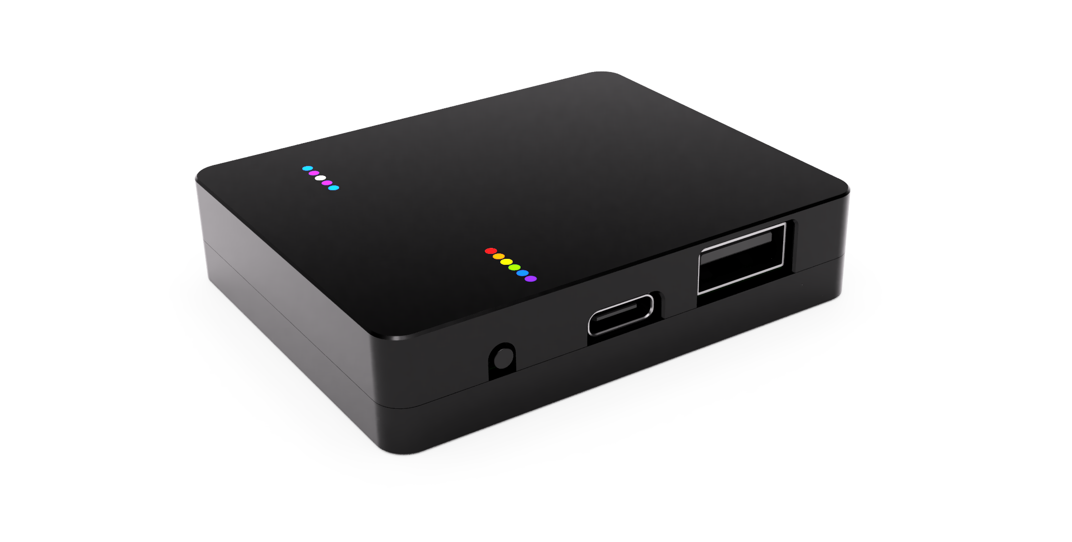
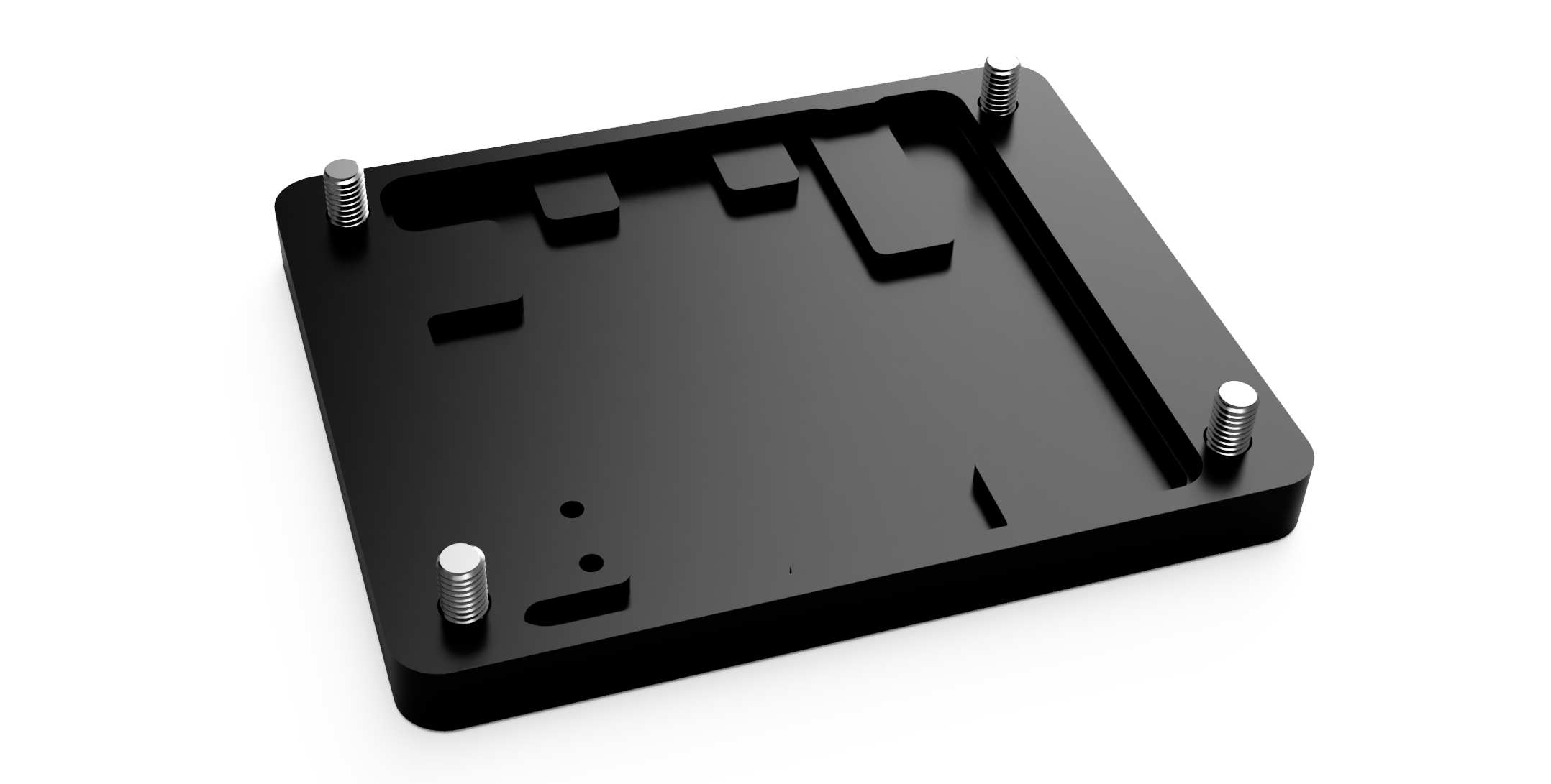
Taylor focused on mechanical aspects of the design, such as creating a prototype enclosure. He also coordinated with contract manufacturers and component suppliers to ensure manufacturability at our target price.
Elizabeth Hendrex planned this Crowd Supply campaign while maintaining business operations and keeping everyone employed throughout the pandemic.
Straithe took the lead on technical support and documentation for all GSG products and projects, including LUNA. She also assumed responsibility for community communication such as these updates, Twitter, and Discord.
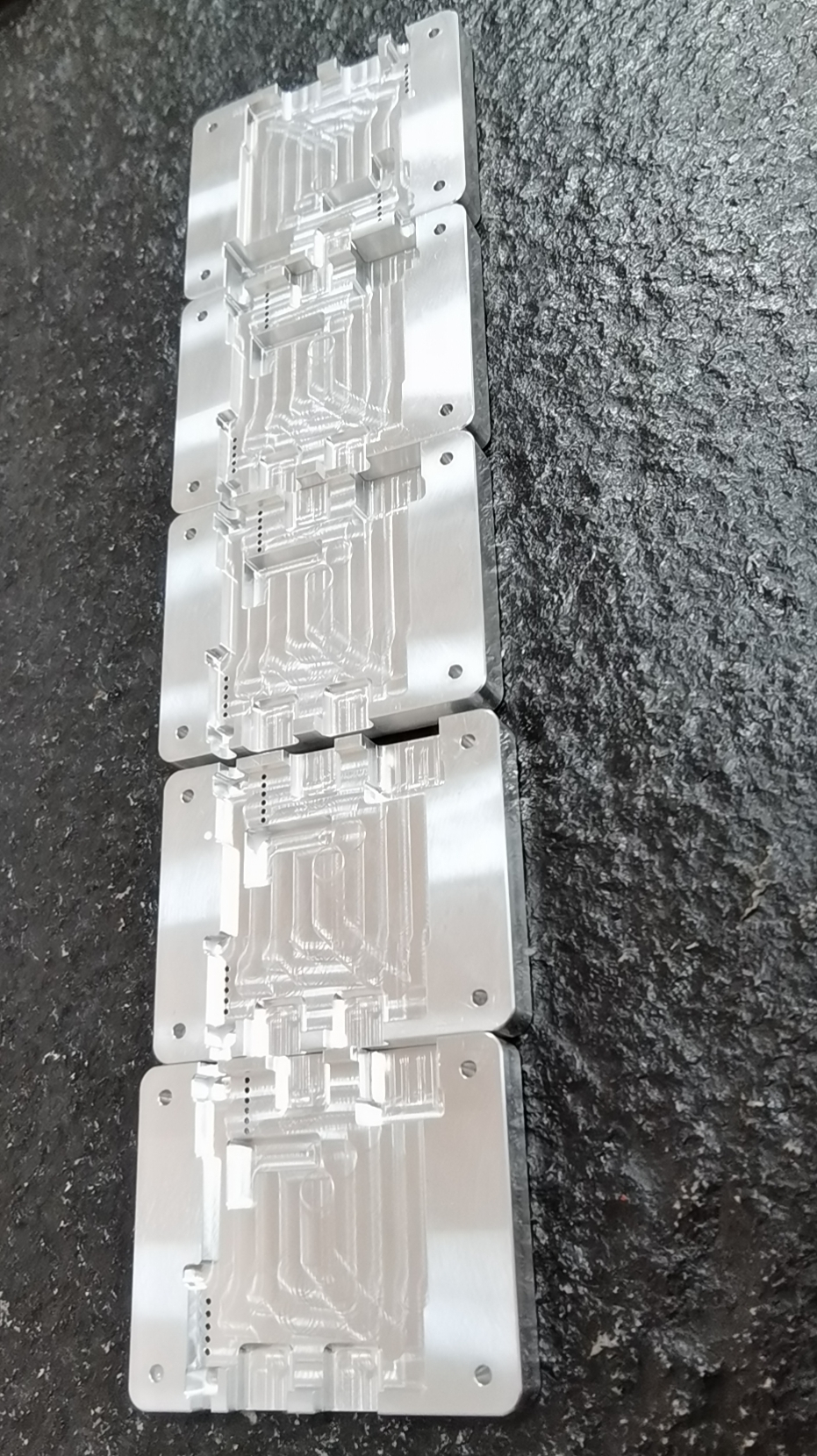
We engaged Timon Skerutsch to design the milled aluminum enclosure and help us with sourcing.
Meanwhile several members of our open source community contributed code to LUNA and related projects, and we launched this campaign as a way for the community to ensure that we will be able to put LUNA into the hands of innovative people. It has been wonderful to witness the team and the community come together to make LUNA a reality!
Thank You
With this campaign we’ve begun a new chapter in LUNA’s history. Kate and Mikaela have recently resigned from their roles at GSG and will no longer be a part of the project. We thank them for the outstanding work they’ve done to make LUNA what it is today, and we look forward to continuing our team effort to bring LUNA’s exciting capabilities to the community. Thank you all so much for your support. We couldn’t do this without you!